I’m perfectly happy with my non-smart LG window air conditioner1, but once in a while I am out of the house, it’s very hot in the city, and I’d like to pre-chill the house before I arrive back home.
That’s where a microcontroller and some firmware come in:
I’m showing toggling the power from my laptop here, but I can change it from my phone, my wife can change it from hers, and we can both do it when we’re not at home by using an iPad as a HomeKit hub.
I haven’t built in the ability to modify the temperature, but we usually keep this set for the season and don’t mess with it a ton, so that hasn’t been a real issue.
I got very, very lucky on this project—my friend Brian wanted to do something very similar with his cassette-style A/C unit, and he actually taught himself enough electrical engineering to design and fabricate a circuit for this task, based around the ESP32, a few sensors, and some hefty infrared LEDs.
He graciously sent me one of his development boards a few years ago to try to get me hooked on the Espressif chips. I was busy with a bunch of other stuff at the time (most notably getting married!) and was frustrated by the complexity of the custom GCC fork-based ESP32 compiler toolchain, and gave up for a bit.
Here’s Brian, writing in June 2021, on the board design:
This was the fourth PCB I designed, and the first “real” one. The first three were practice breakout boards for the various sensors and LEDs I wanted to use, and they served as practice for going through the full KiCad production flow.
First was a TSL4531 breakout board. It consisted of 4 header pins broken out and two surface mount components - the sensor and a decoupling capacitor. I soldered it with solder paste and a hot air station.
Next was a BME280 breakout board. It similarly consisted of 2 surface mount components and was soldered in the same way.
The last one was an LED “test” board which had footprints for various infrared LEDs and its purpose was to test which infrared LEDs on Digikey had the best effective signal range. Contrary to my initial expectations, I found that the narrower emission angles performed much better because they’re more concentrated (of course) but they can also bounce more off of surfaces which provides a higher chance of the signal being picked up.
All boards were ordered and fabricated via OshPark.
I then built the entire circuit on a breadboard with an ESP32 Dev-C dev board along with my previous sensor breakout boards.
Once I was fairly sure it all worked together, it was mostly a matter of wiring all the components together in KiCad’s schematic designer. I also created the PCB footprints for each part as they either didn’t exist at the time or I hadn’t learned where to search/import them. That ended up being useful experience because you’ll often come across parts that don’t have a pre-existing footprints.
I put 3 of the best performing infrared LEDs in parallel, and slapped a 100uF capacitor next to them but this was all based on gut feelings and no actual science :)
I also picked parts quite similar to the ESP32 dev boards, though I avoided tantalum capacitors (usually the yellow ones) because I’ve heard flammability stories around them and thought it was best to just avoid them entirely. The AMS1117 3.3V voltage regulator is commonly used on ESP dev boards so that went in the design as well. A pretty common micro USB socket was used for power (no plans for battery power on this board) along with a fairly generous fuse. A Schottky diode would also be a smart thing to have on the +5V input pin though I haven’t added that yet…
Most dev boards include a USB-serial converter but I decided against that to reduce the part count, so I broke out the RX and TX pins on a header instead. I actually ended up making a separate serial PCB that plugs directly into my main ESP32 board to make development easy.
The board also includes an infrared receiver for reverse-engineering remotes and a reset button.
With all the parts selected and connected in the schematic, I just had to lay it out on a sensible PCB. Phil has told me there’s a Java JAR you can just download and it’ll auto-route the wires magically. I didn’t know about this so I wired everything together manually like an animal. If you go that route, the best thing you can do is lay down ALL the components before drawing a single wire. Once you’ve reasoned about where all your wires will go and how they’ll get around other wires, you can start connecting everything. This process is a lot easier than placing a few components, routing some wires, placing a few more components, routing more wires, realizing you messed up, deleting wires, moving components, and on and on.
Some tips for manual wire layout:
- Try to keep a full ground plane in a 2 layer board. Almost every component needs a GND connection and you can easily get to it with a via. I’ve also heard this can help with EMI and signal integrity but I don’t claim to know anything about that.
- You can use 0 ohm resistors to “hop” over other traces if you’re all out of options. I’ve never done this but it’s nice to know that extra “layer” exists when you need it.
- Use KiCad’s “shove” and “walk around” interactive routing options, it makes it so much easier to places wires quickly and in a neat way.
After I finished up, I simply ordered it via OshPark as I had done with my sensor breakout boards. I soldered it with a combination of regular solder + iron tip, and solder paste + hot air. It amazingly worked on the first assembly and I was ecstatic!
Before setting the project aside, I did get some of Brian’s own test code running and captured the details about the IR signals the remote sends to the A/C unit.
The remote uses the NEC coding. By testing my remote using the IR receiver module and some example code, I found that the buttons on the remote corresponded to the following address and command codes:
power on off:
I (11654) example: Scan Code --- addr: 0x6681 cmd: 0x7e81
I (11704) example: Scan Code (repeat) --- addr: 0x6681 cmd: 0x7e81
temp up
I (2476) example: Scan Code --- addr: 0x6681 cmd: 0x7a85
I (2536) example: Scan Code (repeat) --- addr: 0x6681 cmd: 0x7a85
temp down
I (11736) example: Scan Code --- addr: 0x6681 cmd: 0x758a
I (11786) example: Scan Code (repeat) --- addr: 0x6681 cmd: 0x758a
mode
I (7932) example: Scan Code --- addr: 0x6681 cmd: 0x649b
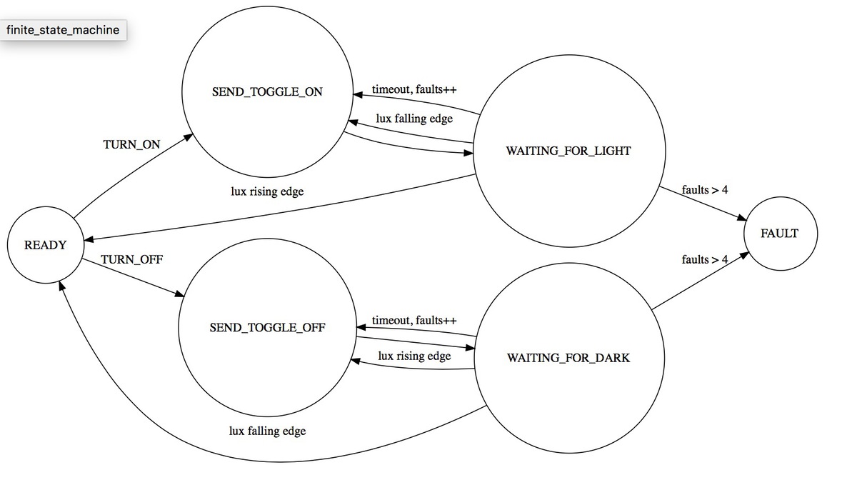
I (7982) example: Scan Code (repeat) --- addr: 0x6681 cmd: 0x649bI also had an idea for how I might “close the loop” from toggling the unit to knowing what state it’s in:
I was very happy I waited, because in the meantime, Apple released a public SDK for HomeKit, which solved the too-much-like-real-work provisioning and remote control aspects of the project in one fell swoop. Espressif pretty quickly released their own SDK for HomeKit which is really well done—the examples literally spit out a QR code to the serial terminal you can use the securely provision the device.
I started from the fan example and folded in some code
from ESP-IDF’s IR examples to send signals to my unit when HomeKit
toggled the “on” characteristic when
changed. About an hour of tinkering one evening got that much
working, which inspired me to just finish the dang project!
Because the controller needs to sit on top the A/C unit, I wanted it to look neat and polished. I designed a case using OpenJSCAD:
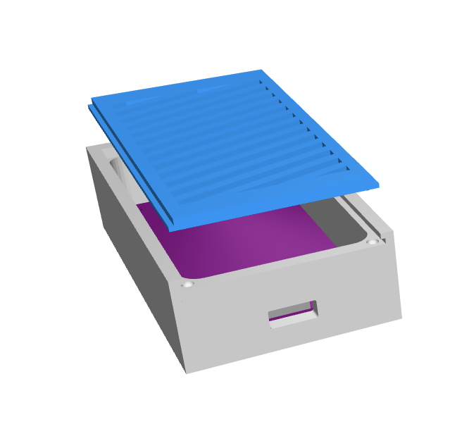
The sliding cover/grille has two balls that fit into two detents in the case, to keep the cover shut and provide a little “click.”
I had this printed via SLS, which worked shockingly well:
Last updated July 11, 2020.
It’s an LG LW1216ER, which is straightforward to install and clean.↩︎